Bolek pisze:Szperam za informacjami o tym układzie i z byt wiele oprucz list społecznych i płytek to nie ma

. Może by zrobić jeden temat o obsłudze tego układu?.
Czy mógł bym prosić o wytłumaczenie funkcji PFD. Jak bym PDFa nie tłumaczył to nie wiem jak to zastosować...
Inna sprawa to to że widze iż na Waszych schematach to wejście jest powiązane z pinem Vref- jakie to ma mieć zadanie? Dawno temu bawiłem sie A3972 i tam wybierało się tryb MIXED lub FAST DECAY zgodnie z aktualnym zboczem prądu w silniku...
troszeczkę już na ten temat dyskutowaliśmy...
allegro w FAQ pisze:Q18 - What does automatic current decay mode detection/selection mean?
The A3977 will automatically select the decay modes suitable for optimum performance. If the output current at the previous step was higher than the output current for the present step, then the PFD pin controls the decay mode (falling current, moving towards zero). If the output current at the previous step was lower than the output current for the present step, then the decay mode is fixed to slow decay (rising current, away from zero). When first powering-up the device, coming out of reset, or coming out of Sleep mode, the device will set both bridges to mixed-decay (PFD controls the decay mode).
obrazki z mana allegro...
Mieszane gaszenie (mixed decay)
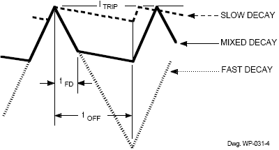
01) wykres gaszenia prądu
02) powolne gaszenie... slow decay
03) szybkie gaszenie... fast decay
04) mieszane gaszenie... mixed decay
allegro w manie pisze:
Percent Fast Decay Input (PFD). When a STEP input signal commands a lower output current from the previous step, it switches the output current decay to either slow-, fast-, or mixed-decay depending on the voltage level at the PFD input. If the voltage at the PFD input is greater than 0.6VDD then slow-decay mode is selected. If the voltage on the PFD input is less than 0.21VDD then fast-decay mode is selected. Mixed decay is between these two levels. This terminal should be decoupled with a 0.1 µF capacitor.
Mixed Decay Operation. If the voltage on the PFD input is between 0.6VDD and 0.21VDD, the bridge will operate in mixed-decay mode depending on the step sequence (see figures). As the trip point is reached, the device will go into fast-decay mode until the oltage on the RC terminal decays to the voltage applied to the PFD terminal. The time that the device operates in fast decay is approximated by:
tFD = RT x CT x In (0.6VDD/VPFD)
After this fast decay portion, tFD, the device will switch to slow-decay mode for the remainder of the fixed off-time period.
allegro w innym manie pisze:Mixed-Decay Operation. Automatic mixed decay is a key feature of the A3977. Automatic mixed-decay operation optimizes the current chopping mode in order to achieve the best sinusoidal current waveform for microstepping.
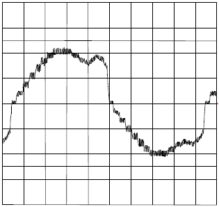
Slow decay (figure 7) has the advantage of minimum current ripple. However, when microstepping at higher step rates, slow-decay chopping may fail to properly regulate current on the falling slope of the sine wave when current is decreasing. This is a result of motor BEMF overriding the voltage applied to the motor, forcing the current to increase during the decay period. Figure 8 is a scope plot of motor current that illustrates the limitations of slow-decay chopping. This distortion in the current will cause increased audible noise in the motor.
...
Fast decay (figure 7) solves the current-regulation problem of slow decay. With almost the full supply across the motor winding it has the ability to quickly get the current out of the winding. The disadvantage of fast decay is the increased current ripple, which in turn causes
increased motor heating. Mixed decay (figure 7) splits the fixed-off time of the PWM cycle into fast and then slow decay. When the current reaches ITRIP, the device will go into fast-decay mode until the voltage on the RC terminal decays to the voltage on the PFD terminal (VPFD). The time that the device operates in fast decay is approximated by:
tFD = RT x CT x ln (0.6VDD/VPFD)
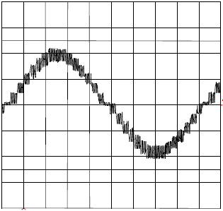
After this fast-decay portion (tFD), the device will switch to slow-decay mode for the remainder of the fixed-off time period. The result is low current ripple, but with increased bandwidth to track the ideal sine wave for microstepping. Although mixed decay improves microstepping performance it will still have higher current ripple than slow decay. The best solution is to use a slow decay on the increasing slope of the sine wave and mixed decay on
the falling slope of the sine wave output, which the A3977 does automatically. When a step-command signal occurs on the STEP input the translator automatically sequences the DACs to the next level. If the new DAC output level is lower than the previous level then the
decay mode for that H-bridge will be set by the voltage Figure 8. Slow-Decay Motor Current
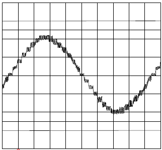
level on the PFD input (fast, slow, or mixed decay). If the new DAC level is equal or higher to the previous level then the decay mode for that H-bridge will be slow decay (see figures 2 thru 5). Figure 9 is a scope plot of the A3977 motor current with slow decay on the rising slope and mixed decay on the falling slope. For comparison, included is a motor current scope plot (figure 10) of the A3977 set to 100% fast decay on the falling slope of the
sine wave and slow decay on the rising slope.
tyle na temat PFD... czyli gaszenia przy czopowaniu napisali w allegro
 http://www.allegromicro.com/datafile/3977.pdf
http://www.allegromicro.com/techpub2/stp/stp01-2.pdf
http://www.allegromicro.com/faq/3977faq.htm
http://www.allegromicro.com/datafile/3977.pdf
http://www.allegromicro.com/techpub2/stp/stp01-2.pdf
http://www.allegromicro.com/faq/3977faq.htm
reasumując - najlepiej ustawić wejście PFD [9] układu w zakresie (0.21 x VDD, 0.6 x VDD)... czyli w trybie
mixed-decay - mieszanego gaszenia
jeśli przymiemy 0.5 x VDD - będzie dobrze... tak zostało ustawione w projekcie z wątku:
https://www.cnc.info.pl/viewtopic.php?p=15414
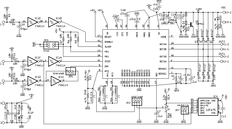
0.5 x VDD robi dzielnik rezystancyjny R10 (4k7) / R13 (4k7)
JP2 ma wspomagać pomiary...


")


")